Current Path Circuit
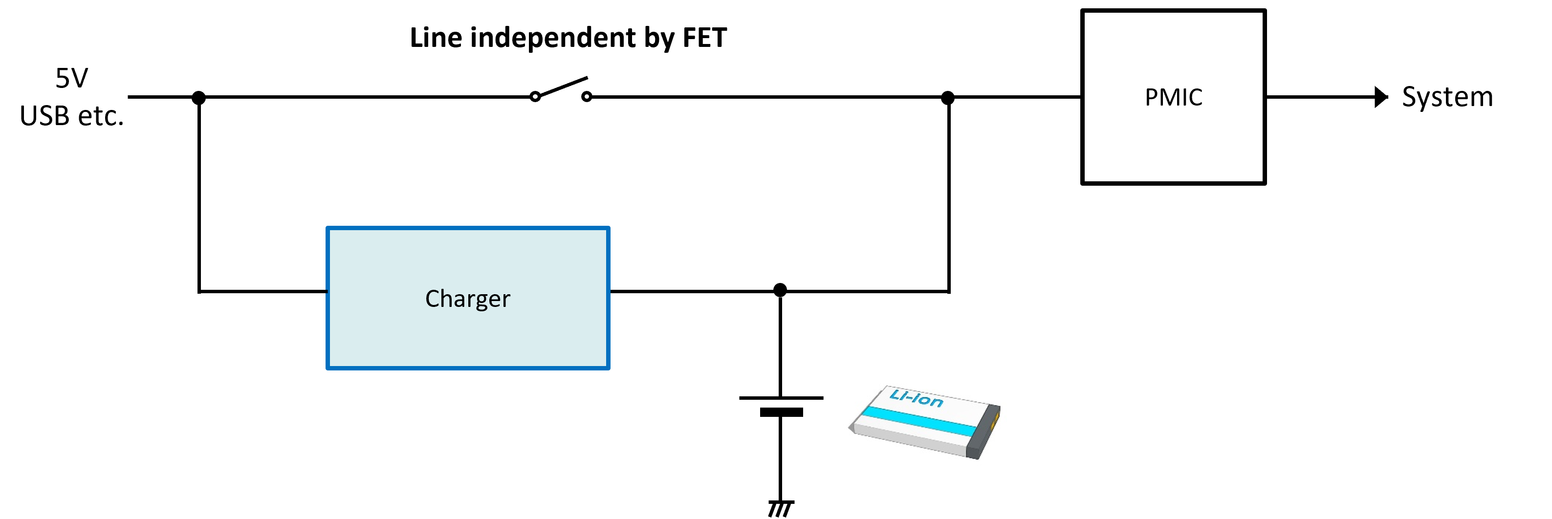
A current path is function to directly supply power to the system side from the input power source (USB, etc.) even during battery charging. The system can also be operated at the same time while the battery is charging. This is optimum for devices that uses communication functions “during charging” or backup circuits, etc.
Issues and Purpose
If there is No Current Path
- Power is supplied to the system side via the battery regardless of whether connected to an input power supply, such as a USB, causing the load current to repeatedly charge and discharge the battery causing the battery to deteriorate quickly.
- When an input power supply is connected: The maximum current is limited to the charge current because the power is supplied to the system side via the charger IC.
Advantages of Adding a Current Path Circuit
Adding a current path circuit makes the supply line to the system side independent from the battery charging line. The advantages are listed below.
- Repeated battery charging and discharging by the load current is reduced to limit battery deterioration.
- When an input power supply is connected: Current is supplied to the system side without the maximum current being limited to the charging current.
This material introduces the method to implement a current path circuit using external components, the advantages and disadvantages, and an overview of operation.
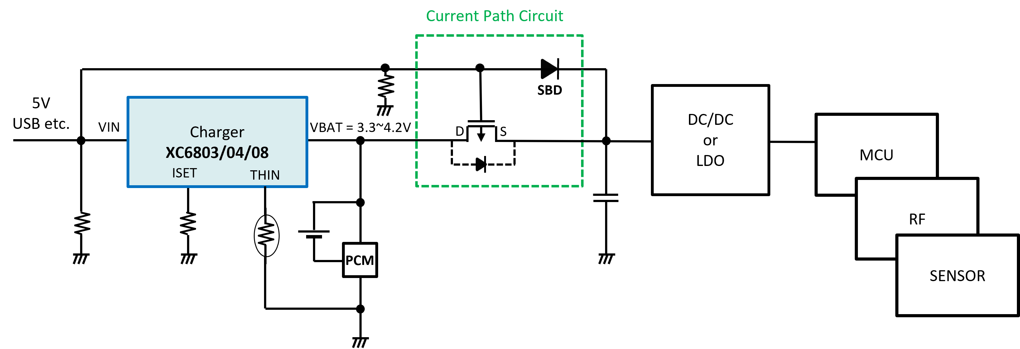
Method to implement
This explains a method for adding a current path function using just a few external components even when the current path function is not equipped with a charger IC.
Advantages
- The system can be used during charging even when using an inexpensive charger IC that does not have a current path function.
- Battery deterioration is prevented by reducing the number of Li-ion/polymer battery charging and discharging cycles.
- During a USB connection a current greater than the charging current can be supplied to the system without passing through the battery.
Disadvantages
- The peripheral circuit becomes larger than a charger IC with a built-in current path function.
Overview of Operation
This explains the operation for when an input power supply is connected and not connected to a configuration to which a current path has been added.
When an input power supply is connected
Path 1: The current is supplied to the load side from the input power supply via the SBD.
Path 2: The Li-ion/polymer battery is charged by the input power supply via the charger IC.
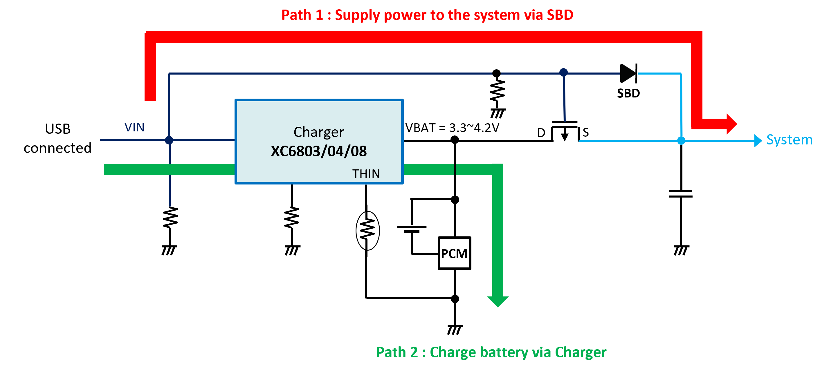
When an input power supply is connected, the power is supplied to the load without passing through the battery, which allows a current greater than the charger IC's charging current and Li-ion/polymer battery’s maximum charging current to flow
Further, the Li-ion/polymer battery can be charged at the same time, so the battery is charged when the USB is connected and power is supplied from the charged battery when the USB is not connected.
When the USB is connected, turn OFF the Pch FET between the Li-ion/polymer battery and the load side.
In addition, the configuration place the source on the system side, which has a higher potential, so that the current does not flow to the Li-ion/polymer battery via the parasitic diode.
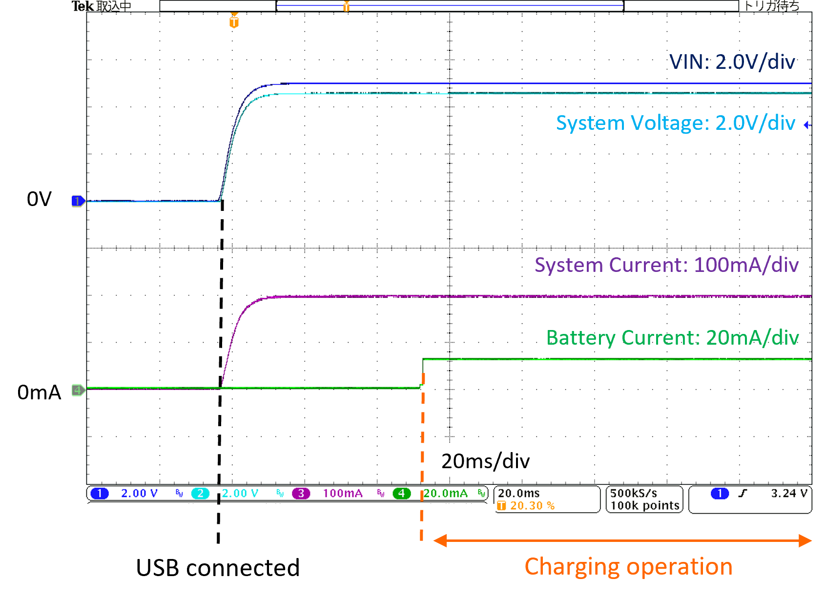
Fig. 3. shows the operation waveform when an input power supply is connected.
t can be seen from the above operation waveform that current can continue to be supplied from the load to charge the battery. Further, the difference between the VIN voltage and the system voltage is due to the drop of the VF portion of the SBD.
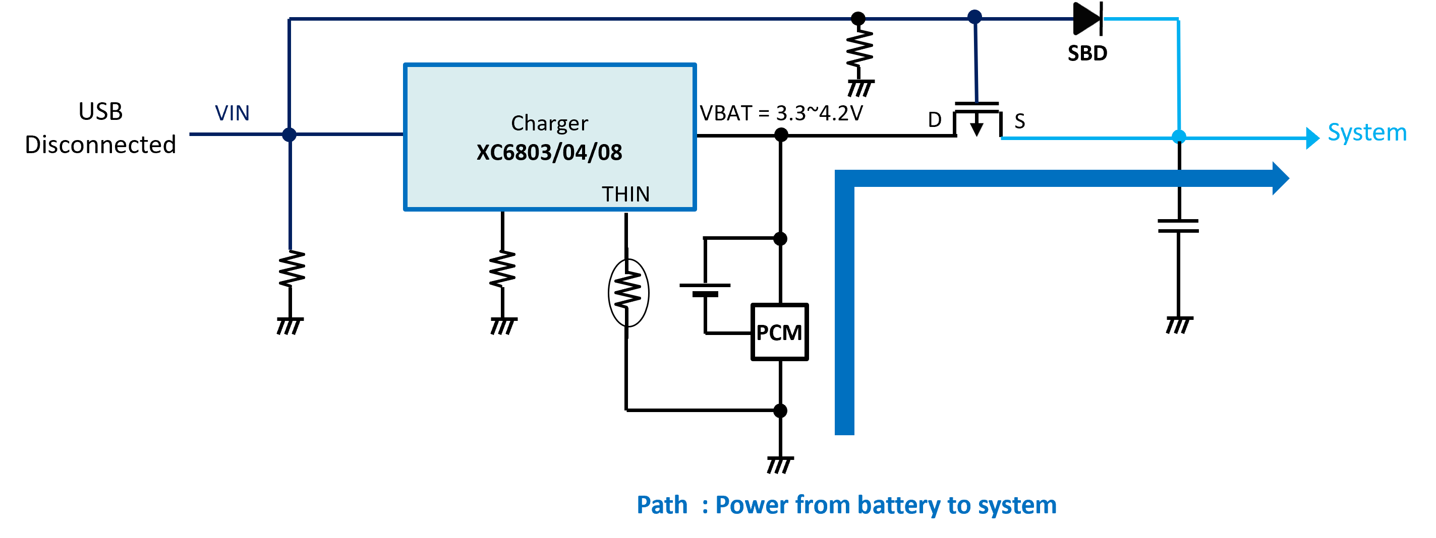
When an input power supply is not connected
Path 1: The Pch FET is ON and power is supplied from the battery via the Pch FET.
When an input power supply is not connected, the current is supplied to the load side from the battery, so caution is required because the maximum value of the load current becomes the battery's maximum discharge current.
Fig. 5. Shows the operation waveform when the input power supply is lost.
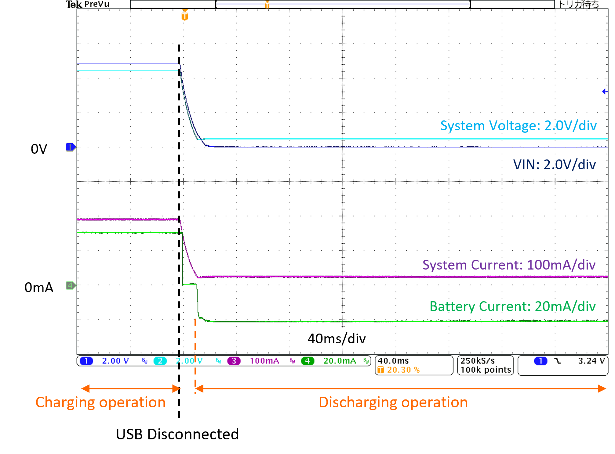
When the input power supply is lost, can be seen that current is supplied to the load from the battery. The minus for the battery current shows a discharge from the battery.
List of Products that Can Use This
| XC6803 | 40 to 280mA, 4.20V, 1-cell Li battery charger IC with a battery temperature detection function |
|---|---|
| XC6804 | 200 to 800mA, 4.20V, 1-cell Li battery charger IC with a battery temperature detection function |
| XC6808 | 5 to 40mA, 4.20V/4.35V/4.40V, 1-cell Li battery charger IC with a battery temperature detection function |
Conclusion
Adding a few external components to even an inexpensive charger IC without a built-in current path function realizes a current path function that can be used to form circuits that are not limited by the charging current and that prevent battery deterioration to extend its life.
PDF Download
External Current Path Circuit that Uses a Simple Function Charger IC [0.5MB]