What is OR connection?
For a device that uses two or more power supply input sources, it is necessary to switch the input sources according to the situation.
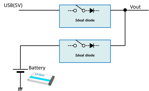
The simplest method for switching the input sources is diode OR connection.
With the diode OR connection, the output power is supplied from the input source with the highest voltage and the input source is automatically selected by the diode when multiple input sources are connected.

Problems and purposes
The diode OR connection is reasonable and simple and it is a method used for a lot of circuits. However, the diode OR connection has also disadvantages due to use of diode.
- Loss and heat generation caused by the forward voltage VF of a diode are large and the battery driving time is shortened.
- Output voltage decreases and the fluctuation becomes large due to voltage drop of forward voltage VF leading to malfunction of the system.
- The leak current of the diode is large and it may adversely affect the anode side of the diode. This is because there is a primary battery on anode side of diode and the current may flow into the primary battery side, for example.
Because of these disadvantages, a method that eliminates the disadvantages of diode OR connection is required for backup applications you want to extend battery life and applications you want to supply stable output voltage.
How to realize
Replacing a diode with ideal diode IC in the diode OR connection can eliminate all disadvantages of diode OR connection.
This method is an optimum OR connection in many cases because it can eliminate disadvantages of diode while the circuit configuration is simple in the same way as that of diode OR connection.
In addition, the ideal diode IC is equipped with protection functions. It is easily possible to design safer devices.
Advantages
- Low loss due to such a small VF; 20 mV & low leak current
- As VF is small, the output voltage fluctuation is small and it contributes to stable operation of system
- Power source switching control circuit is not necessary and simple design is available
- Equipped with various built-in protection functions
- Control circuit is not necessary and small package
Disadvantage
- Maximum output current and output voltage are restricted
Overview of operation
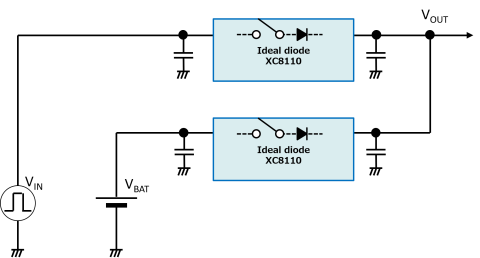
We conducted an experiment to see how much the characteristics vary with "diode OR connection using discrete diode" and "diode OR connection using ideal diode IC" assuming an actual OR connection between 5 V external power supply such as AC/DC adapter and a secondary battery.
Experiment 1-1: Switching of power supplies
We confirmed whether the system voltage could be smoothly switched to the battery voltage by connecting / disconnecting the external power supply with circuits shown in Figures 1 and 2.

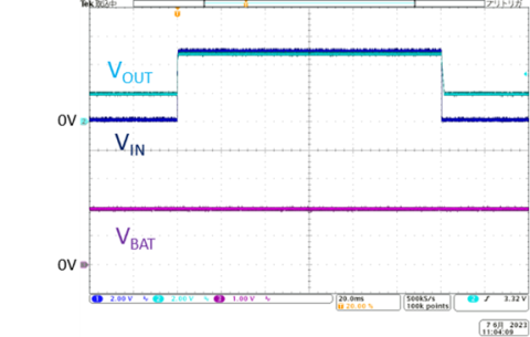
OR connection circuit using SBD
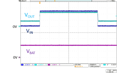
We could confirm that the voltage was smoothly switched with both OR connection circuits as required for OR connection circuits.
・ If 5 V external power supply (VIN) becomes higher than the battery voltage (VBAT), Vout is switched to the external power supply
・ If 5 V external power supply (VIN) is lost and it becomes lower than the battery voltage (VBAT), Vout is switched to the battery voltage
With the OR connection circuit using an ideal diode IC, the system voltage may fluctuate at switching depending on fall / rise speed of external power supply or responsiveness of ideal diode IC, etc. In this case, it is necessary to suppress the fluctuation of output voltage by increasing the output capacity, for example.
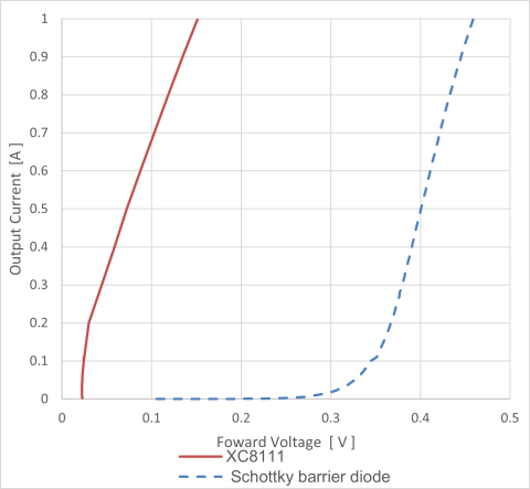
Experiment 1-2: forward voltage
As can be seen from the results of experiment 1-1, with ideal diode IC, input voltage and output voltage are almost equivalent and the voltage rarely drops. A graph of actual relationship between forward voltage and output current is shown below.
With this characteristic, the loss at diode part is small and the voltage drop is small, so the stable voltage can be output.
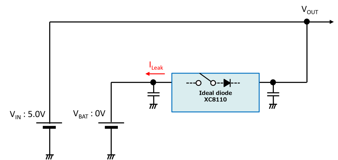
Experiment 1-3: Current leakage
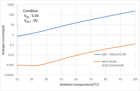
With the ideal diode IC, the current leakage (current that flows from cathode side to anode side of usual diode) rarely flows. It was actually measured with the following circuits.
This characteristic can reduce the loss due to current leakage and prevent backflow to battery at the same time.

The results are shown below.
Conclusion
This paper introduced that high-performance OR connection circuits could be easily configured by using an ideal diode.
There are products that can further reduce current consumption and increase current consumption by using this circuit.