Here explains internal circuit / operation of voltage detector in each status.
In addition, clarifies the operation in each status referencing an example of voltage detector with "L" output at the time of detection, Nch open drain output, and monitoring voltage = input voltage.
A) Release status (detect voltage < input voltage)
If the input voltage is higher than the detected voltage you set, the output driver FET will be turned OFF (Hi-Z) via comparator and inverter.
As the output driver FET gets turned OFF, RESETB terminal voltage becomes pull-up voltage and "H" output.
In the release status, FET that short-circuits the resistance R3 is turned OFF, so the detect voltage depends on the resistances R1, R2, and R3.
A)State before detection (= release state)
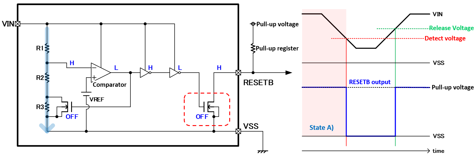
・RESETB pin outputs “H” : Release state
・Detect voltage set by R1, R2 and R3 :
Detect voltage = VREF × (R1 + R2 + R3) / (R2 + R3)
B) Release status → detection status
If the input voltage decreases and becomes detect voltage or less, the output logic of comparator gets inverted. If the output logic of comparator is inverted, the output driver FET gets turned ON and RESETB voltage terminal decreases to 0 V to become "L" output.
B)When VIN drops to the detect voltage
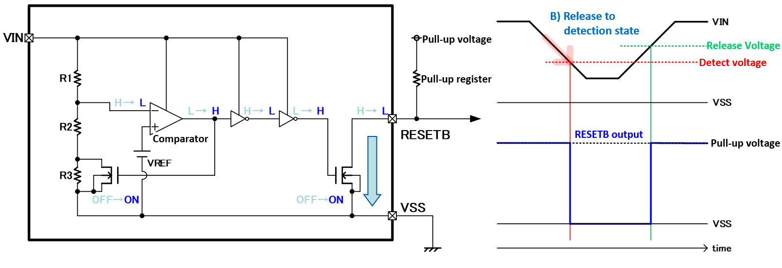
・The comparator is inverted with the values set by R1, R2, and R3,
and the logic of the entire circuit is inverted.
→ RESETB pin inverted to “L”.
C) Detection status (input voltage < detect voltage)
In the detection status (input voltage is lower than the detect voltage), FET that short-circuits the resistance R3 gets turned ON. As this FET is turned ON, the release voltage depends on the resistances R1 and R2.
If FET that short-circuits the resistance R3 is turned ON, a difference between detect voltage and release voltage occurs. This voltage difference is called hysteresis width.
C)Detection state
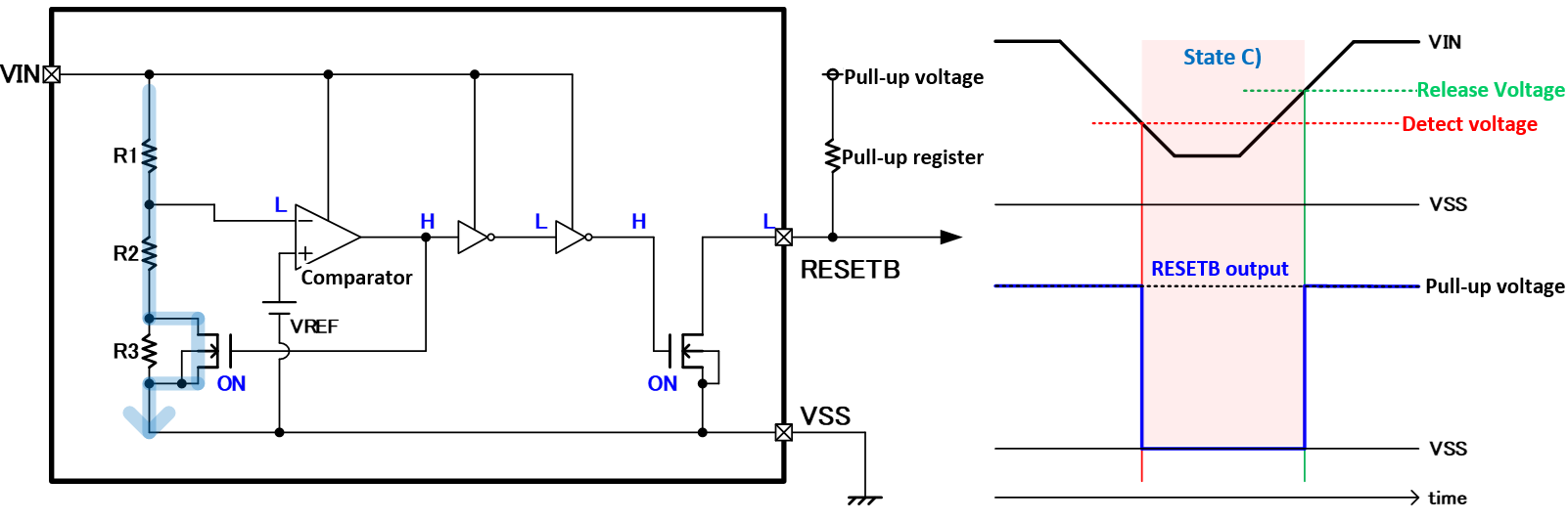
・RESETB pin outputs “L” = Detection status
・Release voltage set by R1 and R2 :
Release voltage = VREF × (R1 + R2) / R2
D) Detection status → release status
If the input voltage increases and exceeds the release voltage, the logic of comparator will be inverted and the output driver FET will be OFF.
As the output driver FET gets turned OFF, RESETB terminal voltage becomes pull-up voltage and "H" output.
D)When VIN rises to the release voltage
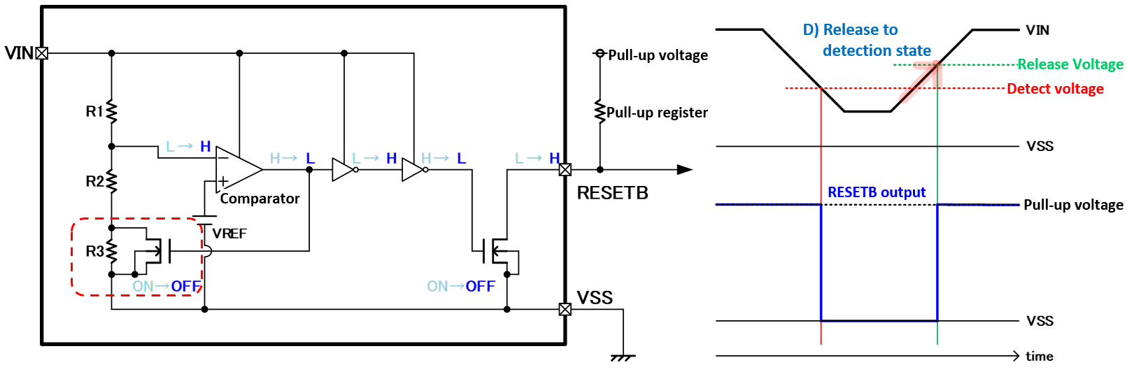
・The comparator is inverted by the value set in R1 and R2,
and the logic of the entire circuit is inverted.
Release voltage = VREF × (R1 + R2) / R2
・RESETB pin outputs “H” ⇒ Outputs pull-up voltage ⇒ Returns to the release state of A)