There are many types of devices that use dry batteries, but in addition, many small IoT devices, security devices, and industrial sensors use primary batteries which are non-rechargeable.
The expected lifetime can still be long, so the power management solution chosen must have ultra-low power consumption to ensure efficient use of the battery to extend the operational lifetime.
Torex offers may ultra-low power IC and in the example solution circuit we demonstrate a function that cuts the power consumption by disconnecting the battery during transportation and when the device is not in use.
Block Diagram(a) See the Solution Summary↓
Block Diagram(b) See the Solution Summary↓
Appendix:Li primary battery
3.0V: Manganese dioxide type / 3.6V: Thionyl chloride type
| Block diagram | Requirements | Recommended ICs | Features |
|---|---|---|---|
| Push Button Load SW To cut battery power rail |
Specifications Other points
|
XC6194 |
Push Button Intelligent Load SW
VIN: 1.8~6.0V |
| Step-up/LDO For RF/Sensor |
Specifications Other points
|
XCL102 / XCL103 (XC9141 / XC9142) |
Inductor built-in step-up DC/DC, PWM (XCL102), PWM/PFM (XCL103)
VIN: 0.9~6.0V |
| XC6233 (XC6215) |
Fast transient response / high PSRR voltage regulator
VIN: 1.7~5.5V |
||
| RESET To monitor battery voltage |
Specifications Other points
|
XC6136 |
Ultra low consumption RESET
VIN: 0.4~6.0V(MIN Voltage Holding the detection) |
Solution Summary
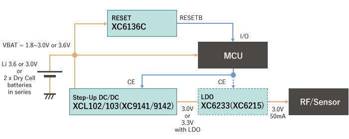
The block diagram (a) shows a typical application where the microprocessor (MCU) is directly connected to the battery. This architecture is often used for simple IoT devices, wearables and medical products.
In recent years, the operating voltage range for MCU has also become wider and 3.3 V ~ 1.8 V or lower is now common place. As a result may MCU can now be connected directly to the battery without needing additional power supply IC.
Step-up IC
However, Radio IC and Sensors often still require a fixed 3.3V supply and even if the operating voltage is wider, the supply Voltage needs to be carefully controlled and often the devices work better at higher Voltages, therefore a step-up DC/DC is sometimes necessary to boost the battery Voltage.
Normally, Radio IC and Sensors are not operated continuously and the application firmware will be used to turn them ON and OFF as needed. For example a Radio IC may only need to transmit and receive one time per day, possibly only for a few seconds, so it is more efficient to turn off the IC for the rest of the time to prolong battery life.
During standby or sleep mode, when the Radio IC and Sensors are OFF and disabled, the operation of the power mangement IC used to supply them will also be turned OFF to conserve energy. This can be controlled easily using the devices CE or EN pin.
Fixed frequency PWM mode ensures maximum efficiency at higher output loads and offers the lowest output ripple with easier noise management.
Alternatively PFM/PWM automatic switching can be used for improved efficiency during light loads. An inductor built-in type is also available, with better EMI suppression and smaller PCB area.
Step-up DC/DCs
XCL102: PWM, inductor built-in type
XCL103: PWM/PFM, inductor built-in type
XC9141: PWM, external coil
XC9142: PWM/PFM, external coil
LDO
Low Drop Out (LDO) Voltage Regulators are often used to clean up a supply rail immediately after a DC/DC. The aim is to reduce noise and interference in the power supplies to the Radio and Sensors.
For these Regulators, High Speed operation, with high levels of Power Supply Ripple Rejection (PSRR) is important together with Low Output Noise and fast transient response performance. With Torex 'Green Operation' (GO) the designer can combine these attributes with ultra-low quiescent current, because GO LDO will adapt their performance to the required output load.
In some cases, the noise performance at higher frequencies can be important and in these instances a simple low speed, low quiescent current LDO may be a better choice.
Voltage regulators
XC6233: High speed
XC6215: Low power
RESET IC
A RESET IC or Voltage Supervisor, is often used to monitor the battery Voltage, if the Voltage drops below a predetermined level the RESET IC generates a signal for the MCU. These devices are always operating, so ultra-low quiescent current is an important consideration.
If the MCU Voltage is the same as the monitored Voltage, a CMOS Output type can be used. The CMOS Output does not require an external pull-up Resistor which helps to reduce unnecessary losses.
When the MCU Voltage is different to the monitored Voltage an N-ch Output type should be used. An N-ch Output type will need an external pull-up Resistor and this will result in slightly higher current consumption across the resistor during reset.
Some MCU have a built-in Under Voltage Lock Out (UVLO) or Analog to Digital Converters (ADC) which can be used to monitor the supply Voltage. However, it is often advantageous to have a separate IC to monitor critical Voltages independently of the MCU.
Voltage detector
XC6136 Type C: Iq - 100nA (Type C: CMOS output)
Solution with improved battery life / push-button load SW
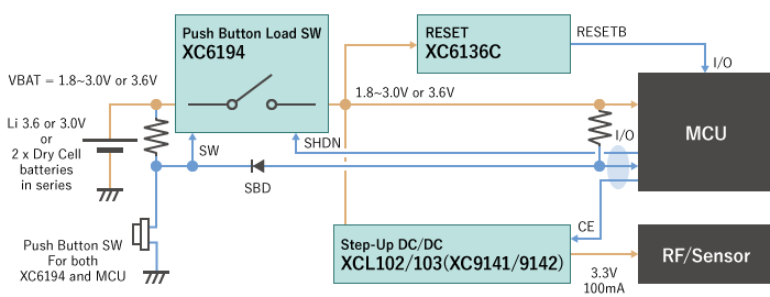
Block diagram (b) illustrates how a Push-Button Load Switch IC can be used to help maximise battery life, by disconnecting the battery from the rest of the circuit.
The Schottky Barrier Diode (SBD) to the right of the SW pin in the diagram and the pull-up resistor to the VDD of the MCU are implemented so the push button can be shared with the MCU.
Push-button load switches
XC6194: 1A built-in SW
XC6193: External Pch-driven, compatible with large currents
This solution has the following significant benefits.
1. Prevents battery discharge during shipment or when the unit is stored in the warehouse before sale.
Often referred to as "Storage Mode" or "Ship Mode" the Shutdown function is ideal for devices where the batteries cannot be removed for safety reasons. The quiescent current in "Storage Mode" is essentially "0".
A device in "Storage Mode" can be enabled by pressing the push button SW.
2. Push-Button Load Switch IC can be used to turn the main power supply ON and OFF.
The ON/OFF control can be performed by push-button rather than a mechanical switch and this is often preferred for applications which need to be waterproof or water-resistant.
The MCU sends a signal to the SHDN pin of the Push-Button Load Switch IC to turn off the main system power supply rail. The power can later be restored when the user presses the push-button switch.
It's also possible to enable the Shutdown function by pressing and holding the push-button for a predetermined period of time. Different options are available, so please consult the date sheet for more details.
3. Escape from system freeze or system malfunction
When a device freezes and the system firmware locks up, the only remedy is often a fully system reset. This can be achieved by turning the power OFF and ON by disconnecting the battery or main system power using the Push-Button Load Switch IC. Normally this involves the user pressing the push-button for a predetermined period of time which will enable the SHDN function. Is a longer push button hold time is selected (say 5 or 10 seconds) this will lower the possibility of accidental resets.
The device can easily be re-started by pressing the push-button again.
Push-Button Load Switch IC also offer the following additional benefits:
- Suppression of in-rush current during start-up with in-rush current prevention function
- The Power Good (PG) pin can be used to enable the next phase of the start-up sequence once the main power rail is established.
- When the battery Voltage goes below 1.2V the UVLO will force the Shutdown fuction to disconnect the battery for the system to prevent deterioration and battery fluid leakage.
- If the VOUT drops significantly, the Shutdown function will be activated automatically to protect against short circuits.
The performance of simple devices where the MCU is directly connected to the battery can be enhanced by utilising a Push-Button Load Switch IC to prolong battery life and provide additional protection functions.