Unlike voltage regulator, efficiency and loss of DC/DC converter vary depending on control method and characteristics of IC (current consumption, oscillation frequency, on-resistance of driver FET etc.), constants and characteristics of peripheral components.
For this reason, it is necessary to select peripheral components giving consideration to efficiency, mounting area, and cost, etc.
First, here explains how to use loss / loss ratio graph of DC/DC converter.
Next, each item and parameters affecting the loss will be explained to indicate the guidelines for selecting appropriate IC and peripheral components.
1. Loss of DC/DC converter
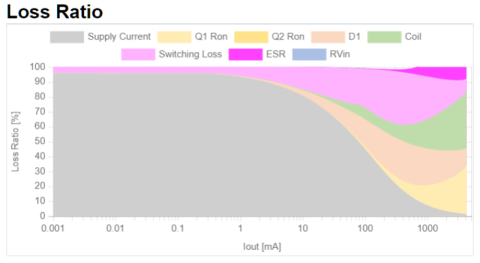
The loss of whole DC/DC converter is configured with "conduction loss", "switching loss", "current consumption", "coil loss", and "others". If this total loss is known, the efficiency of each output current can be calculated.
With this tool, you can easily confirm the loss ratio of each loss.
It is possible to efficiently improve the efficiency by comprehending the items with large loss in an area you want to improve the efficiency.
This function can be also utilized for selection of an optimum part giving consideration to cost, etc. by reducing the cost, etc. of peripheral components without affecting the efficiency.
2. Breakdown of loss of DC/DC converter, parameters affecting the loss
(a) Conduction loss
This is a loss that is caused by on-resistance of driver FET or VF loss of diode.
If on-resistance of driver FET and VF of diode are large, the loss becomes large. As the loss caused by on-resistance is proportional to the square of the current, it mainly affects the efficiency at heavy load.
For a product equipped with external FET and diode, the conduction loss can be reduced by selecting a product with small on-resistance and VF. In case of a product with built-in driver FET, the on-resistance cannot be adjusted without changing the product itself.
However, if the on-resistance of driver FET is reduced, the gate capacity becomes large and the current consumption used for driving FET increases. If you select SBD with small VF, the current leakage tends to increase. The efficiency at light load is decreased by the current leakage.
| Q1 Ron | conduction loss occurring in driver FET or external FET Q1 |
|---|---|
| Q2 Ron | conduction loss occurring in driver FET or external FET Q2 |
| D1 | conduction loss occurring in external diode |
(b) Switching loss
This is a loss that is caused at rising / falling of switching node at switching.
The switching loss increases in proportion to voltage amplitude, rising / falling speed, coil current (output current), and oscillation frequency of switching node
As it is proportional to the output current, it mainly affects the efficiency at heavy load.
To reduce the switching loss, following methods are generally adopted.
- Select a product with low oscillation frequency or select peripheral components that reduce it.
- For external FET, reduce the gate resistance.
- Increase the switching speed by reducing the gate capacity of external FET.
If the switching speed is increased, there is a disadvantage that the noise level of radio-frequency radiation increases.
If the gate capacity is reduced, the on-resistance tends to increase for FET with the same process. It is necessary to select an FET giving consideration to balance between switching loss and conduction loss.
With this tool, the loss that occurs in dead time is included with "Switching Loss".
The dead time means the period in which High Side driver and Low Side driver are simultaneously turned OFF. This dead time is deliberately set to prevent the period in which High Side driver and Low Side driver are simultaneously turned ON for Synchronous rectification type DC/DC converter. During the dead time period, the coil current flows into parasitic diode of driver FET to cause a loss.
| Switching Loss | switching loss that is caused at rising / falling of switching node + loss that is caused during dead time |
|---|
(c) Current consumption
This is current consumption to be used for driving of internal circuit of IC and driver FET.
It depends on current consumption and switching frequency of IC, and gate capacity of driver FET. It mainly affects the efficiency at light load.
To reduce the current consumption, following methods are generally adopted.
- Select a product with low current consumption.
- Select PFM control type DC/DC converter to reduce the switching frequency.
- Select a driver FET with small gate capacity.
For current consumption, control method, and switching frequency of IC, a DC/DC converter to be selected is important.
If the gate capacity is reduced, the on-resistance tends to increase for FET with the same process. It is necessary to select an FET giving consideration to balance with conduction loss.
| Supply Current | Current consumption used for operation of internal circuit of IC and driving of driver FET |
|---|
(d) Coil loss
This is a loss caused by coil.
The loss is mainly caused by DCR and ACR, etc. of coil.
DCR is DC-like resistance component. If the coil current increases, loss occurs in proportional to the square of the coil current. It mainly affects the efficiency at heavy load.
ACR is AC-like resistance component. If the frequency increases due to the skin effect, etc., the resistance component increases. It mainly affects the efficiency at PFM with large amplitude of coil current and small DC current.
For some inductors, ACR characteristics can be confirmed with the website of the inductor manufacturer.
On this tool, it is not possible to input ACR. It is designed to keep constant magnification of DCR.
If you want to conduct simulation by inputting ACR, please contact TOREX separately.
| Coil | loss due to DCR, ACR, hysteresis loss of coil |
|---|
(e) Other
This is a loss other than above.
This tool calculates the losses due to resistance component of input line (Rvin) and ESR of output capacitor as losses other than above.
If the resistance value is large, the resistance component of input line (Rvin) affects considerable reduction of efficiency or maximum output current. It is necessary to carry out design taking it into consideration.
| ESR | loss caused by ESR of output capacitor |
|---|---|
| Rvin | loss caused by resistance component of input line |