

Comparison with a linear regulator
One of the main characteristics of the DC/DC converter is its high power conversion efficiency. Its significantly higher efficiency compared to a linear type voltage regulator is also known.
Why can the DC/DC converter achieve this high an efficiency?
Firstly, let's look at how the linear type voltage regulator and the DC/DC converter cause power loss during actual operation.
Power loss in a linear type voltage regulator
A linear type voltage regulator controls the output voltage by continuously adjusting the on resistance of the driver FET (or the transistor) that is between the input voltage and output voltage.
Specifically, when the voltage is dropped from the input voltage to the output voltage, the driver FET functions as a resistor and the following power loss occurs depending on that resistance component and the output current.
This power loss cannot be avoided as it is due to the operating principles of the linear type voltage regulator.
Power loss = (input voltage - output voltage) × output current
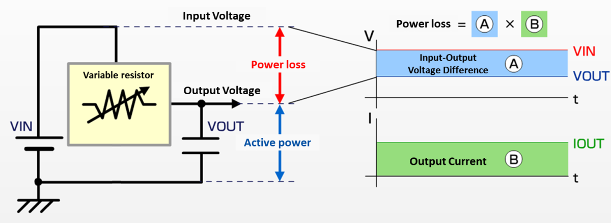
In a linear regulator, the product of the voltage difference between the input and output (A) and the output current (B) is the power dissipation as is.
The more the output voltage is set lower than the input voltage, the greater this voltage difference, which results in an increase in the power loss.
This is the main reason for the low efficiency, due to the extra power being expended as heat.
Power loss in a DC/DC converter (step-down type)
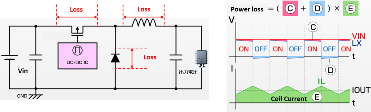
A DC/DC converter is fundamentally different to a linear type voltage regulator, controlling the output voltage by turning the switch element (FET, etc.) on and off at high speed (switching control).
When the switch element is in the on state, a coil current flows in a (low on resistance) FET with an extremely small resistance component, or in a diode with a small forward voltage drop (low VF).
Depending on the current in this on state, the following conduction losses are generated.
FET conduction loss = (coil current)^2 × on resistance
Diode conduction loss = coil current × VF
As indicated in this diagram, the time for which the switch element in the DC/DC converter is in either the on or off state accounts for the majority of the time.
When the switch is on, the voltage drop (C) is extremely small, and when the switch is off, no current flows.
Similarly for the diode, the voltage drop (C) is small when the current is flowing.
The coil current (E) is flowing, but in contrast to the linear regulator in which the switch element always functions as "resistance," the conduction loss of the switch element in the DC/DC converter is kept extremely small.
For that reason, the efficiency of the DC/DC converter is significantly higher than that of the linear type voltage regulator.
(In fact, the entire power loss of the DC/DC converter is the total of the conduction loss of the switch element and coil, the switching power loss, the control circuit's power consumption, etc.
However, the power loss in the switching element which is the major source of power loss is significantly smaller compared to the linear regulator, and so high efficiency is achieved.
Joined Torex Semiconductor in 2005.
After six years engaged in the development of power ICs such as DC/DC converters, worked for three years providing technical support for offline LED drivers.
Later took charge of technical support for Torex’s power IC customers.
With expertise gained through product development and extensive know-how accumulated from years of customer support — including solutions for power-related issues and troubleshooting — currently engaged in providing technical support and product proposals for Torex products.